
Making sense – Civil Engineering Building instrumented with five sensor packages to support performance based design
Funded as part of a £138M UK Government investment in infrastructure and cities research, the new Civil Engineering Building - home to the UKCRIC National Research Facility for Infrastructure Sensing (NRFIS), has been instrumented with five sensor packagesto monitor the whole-life performance of the asset. The sensor packages within the modular building create a live learning research tool.
Academic and research staff from the University's Centre for Smart Infrastructure and Construction (CSIC) have developed the technologies to store, interpret, and visualise the data streams resulting from the sensor systems. This information will be used to monitor and understand the performance of the building components, assess performance against predictions made during design, and inform future design and modification to improve efficient use of materials and reduce embedded and operational carbon. This knowledge is intended to feed directly into the design and construction of future phases of the Engineering Department’s expansion at the West Cambridge site, which will consist of a number of similar buildings.
Context
The global construction industry is worth $10tr annually and creates and maintains the built environment that emits about half of the planet’s carbon emissions. Construction creates the majority of the infrastructure that is essential for trade and commerce. It underpins the productivity of most industries, and the healthiness of building occupants.
Yet despite this, we still know surprisingly little about the real performance of buildings, and their interaction with occupants. This uncertainty results in excess material consumption being a default risk mitigation strategy – resulting in more carbon emissions. The installation of sensors on building components is the first step in a new and virtuous circle of learning that has the potential to shape the way we design future buildings. If, through measurement, we can determine the real demands that are placed on buildings, we can reduce uncertainty and improve future design methods.
Sensor packages
Ground Source Heat Pump (GSHP) boreholes
• Temperature-sensing distributed fibre optic sensor (DFOS) loops in 2 GSHP boreholes 165m deep • Temperature-sensing DFOS loops in 1 sacrificial borehole 175m deep • Total of 1km of DFOS temperature-sensing cables
A distributed fibre optic temperature sensing system (DTS) is installed in two adjacent GSHP boreholes as well as in the ground between them. This system will provide the temperature profile along the depth of the boreholes and the ground, as heat is transferred to and from the building’s GSHP system. The distributed temperature data will be used to assess the long-term performance of the GSHP system and feedback into its efficient operation. It will also allow the detection of possible long-term heat imbalance and associated system efficiency loss. The data will be used to calibrate heat transfer models and estimate the thermal properties of individual geological strata. This will help improve future system design by, for example, optimising the boreholes’ depth, spacing and layout.
Strong floor slab
• 12 DFOS and 13 fibre Bragg grating (FBG) loops (top and bottom of slab) sensing strain and temperature • Total of 640m DFOS sensing cables and 319 FBG sensors • The strong floor is 20m long, 10m wide, 1m thick, weighing approximately 500 tons
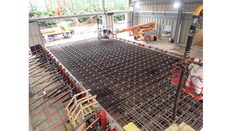
Figure 1: The strong floor instrumented with DFOS and FBG sensors being concreted
A fibre optic sensor system in the post-tensioned reinforced concrete strong floor comprises two sub-systems, each installed in two layers, at the top and bottom of the slab: a distributed DFOS system, providing measurement of distributed strain and temperature, and an FBG sensor system, providing point measurements of dynamic strain and temperature at regular intervals (see Figure 1). The objective of this instrumentation is to enable strain measurement during construction and throughout the life of the strong floor, including: investigating immediate and long-term concrete creep caused by the post-tensioning; quantifying any loss of post- tensioning over the life of the structure thus informing the asset owner if, when and where re-tensioning needs to be carried out; and evaluating the effects of heavy, concentrated and dynamic loading during experiments carried out on the strong floor (see Figure 2).
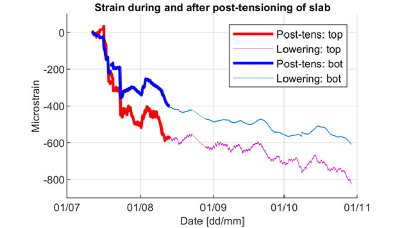
Figure 2: Compressive strain measured from two of the FBG sensors embedded in the strong floor: during (thicker lines) and after (thinner lines) post-tensioning of the slab
Basement raft and perimeter wall
• Two DFOS and two FBG loops installed in the raft (top and bottom of the raft), and seven FBG loops in the retaining walls sensing strain and temperature • Total of 120m DFOS sensing cables and 108 FBG sensors
A fibre optic sensor system is installed in the reinforced concrete raft at basement level (see Figure 3) and in the reinforced concrete walls around the perimeter of the basement, which lies beneath the strong floor. The system comprises two sub-systems installed in parallel: a DFOS system and FBG sensor system to enable the measurement of changes in strain and temperature along selected lines in the raft and walls. This is useful in order to observe the performance of the basement structure as a whole in response to the long-term effect of ground movement (heave on the raft and lateral pressure on the walls) and operational loading, such as when the strong floor above is being heavily or dynamically loaded.
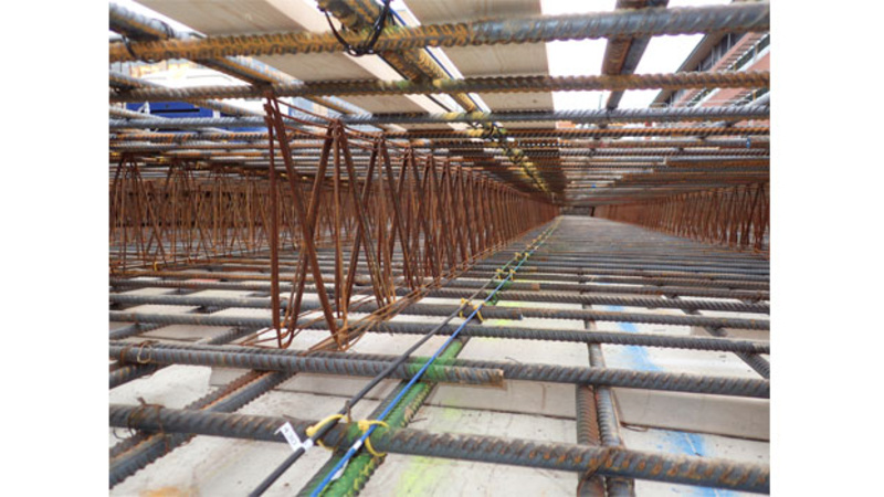
Figure 3: Fibre optic sensor cables attached to the basement raft reinforcement
Frame structure
• A complete frame comprising 12 columns and nine beams instrumented with one FBG sensor pair each (one sensor on each flange), to be monitored continuously • A total of 42 sensors comprising 66 FBGs
An FBG sensor system is installed on the steel structural frame of the building to provide dynamic strain measurement capability at point locations on all columns and beams along one entire cross-section of the structure. In total, 21 members are instrumented (12 columns and nine primary beams). The objective is to measure both static and dynamic axial and bending strain in the primary members of one representative cross-section of the structure. This can be used to monitor vibration and quantify strain (and therefore stress) in the primary structural elements to understand load distribution and structural performance under operational conditions. Providing evidence of structural behaviour could enable more efficient future reconfiguration or additions to the building over the long-term as well as enable the design of subsequent building extensions to be refined.
Blue roof
• Weather conditions, soil moisture content, water level and temperature sensors to assess the effectiveness of the blue roof, as well as providing environmental parameters for the other sensing packages
The building’s blue roof (providing temporary storage and gradual release of rainwater) is equipped with a monitoring system consisting of a weather station, 21 temperature probes installed in three vertical layers at seven locations, 24 soil moisture content sensors and seven water level sensors. The overall aim of the sensing system is to evaluate the effectiveness of the roof in regulating rainwater drainage runoff while supporting healthy vegetation growth and providing additional thermal insulation. By monitoring closely and continually the evolution of the temperature and water retention of the roof in relation to weather conditions, it will be possible to gain a better understanding of the environmental and ecological functions of the roof.
Making sense of sensing
Buildings are often perceived as static inanimate systems, but the potential of sensing and data analytics challenges this perception. Sensors embedded in the structure bring the building to life, making real the possibility of measuring structural health and performance throughout an asset’s life. CSIC have developed a set of tools to provide the means for measuring these vital signs, which are ingrained in the large continuous flux of data recorded by embedded sensors. These data management tools include an efficient data store, flexible communication protocols and modern software architecture, which in turn enable data analysis and data visualisation of the current state of the asset in real time. Among the opportunities presented by this new framework, two powerful features are the generation of knowledge for the performance-based design of buildings and engineering tools driving decision-making for asset management and maintenance.
The online platform developed by CSIC to collect, store and visualise the data streams from the sensor systems is available to view at: http://www.csiclivingbuilding.eng.cam.ac.uk/.
A workshop demonstrating how to navigate the 3D models of the instrumented areas and visualisations of the data is available on the CSIC YouTube channel. This is hosted by CSIC Research Associates Dr Miguel Bravo-Haro, and Dr Nicky de Battista. For further details visit: CSIC online workshop: Bringing Buildings to life
Acknowledgement
The fibre optic instrumentation of the Civil Engineering Building was carried out in collaboration with Epsimon Ltd, who were responsible for the specification, design, and installation of the systems and for monitoring during construction.
The research forms part of the Centre for Digital Built Britain’s (CDBB) work at the University of Cambridge. It was enabled by the Construction Innovation Hub, of which CDBB is a core partner, and funded by UK Research and Innovation (UKRI) through the Industrial Strategy Challenge Fund (ISCF).
Contact: Dr Nicky de Battista, Dr Miguel Bravo-Haro, Dr Cedric Kechavarzi, Paul Fidler, Dr John Orr